
The utility model provides a compensation oil pump for diaphragm compressors with clearer effects, technical specifications, and advantages. The following will provide a systematic description of the technical specifications of this utility model. Obviously, the described embodiments are only a part of the embodiments of this utility model, not all of them. According to the embodiments in this utility model, all other implementation methods obtained by general professional technical personnel in the industry without any creative labor belong to the scope of maintenance of this utility model.
The utility model provides a compensation oil pump for a diaphragm compressor, which includes an oil pump body 1. The bottom flange of the oil pump body 1 is connected to an oil inlet valve 2, and one side of the oil pump body 1 is provided with an oil inlet hole 3. The oil pump body 1 on the opposite side of the oil inlet hole 3 is equipped with an oil discharge valve 4, and the upper end of the oil inlet valve 2 is equipped with an oil discharge valve 4. The upper edge of the oil discharge valve 4 is connected to a plunger 7 according to the torsion spring 6; The side of the oil inlet valve 2 is equipped with two o-shaped sealing rings 8, and a sealing gasket 9 is arranged between the top port of the oil inlet valve 2 and the internal step surface of the oil pump body 1 for sealing.
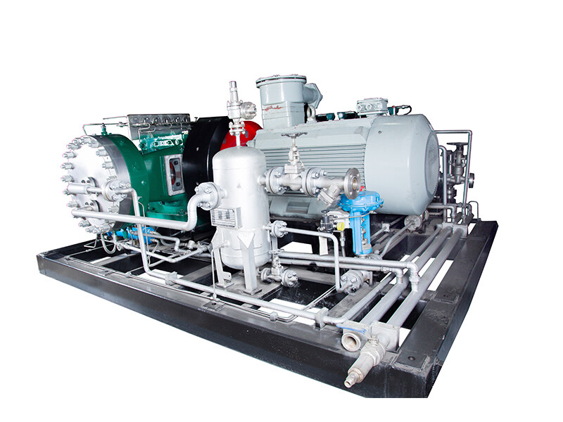
The upper end of the oil pump body 1 is also embedded with a plunger sleeve 10, and the top of the plunger sleeve 10 is equipped with a plunger gland 11. The plunger gland 11 is cross connected with the oil pump body 1 according to the cross countersunk head bolt 12; The plunger 7 is located within the plunger sleeve 10, and can be moved back and forth from within the plunger sleeve 10. The J-shaped sealing ring 8 is selected between the plunger sleeve 10 and the plunger 7 for sealing.
The bottom bolt of inlet valve 2 is connected with a clamping gland 14. The above clamping cover 14 is used to clamp the oil inlet valve 2. A second sealing gasket 15 is arranged between the clamping cover 14 and the lower port of the oil pump body 1. The oil pump body 1 is also equipped with a spring seat 17, which is located between the oil discharge valve stop 5 and the torsion spring 6.
Oil enters through the inlet hole 3 during the travel of plunger 7, and enters the capacity chamber 16 at the lower end of plunger 7 according to the shift of inlet valve 2 and drain valve 4. During the downward travel arrangement of plunger 7, the compressed oil in the capacity chamber 16 is discharged from the drain valve 4; When the plunger 7 is in the up stroke, the fourth gear of the oil discharge valve is in the open state, and the compressed oil enters the capacity chamber 16; When the plunger 7 is in the down stroke, the fourth gear of the oil discharge valve is closed, and the compressor oil is discharged from the capacity chamber 16 through the oil discharge valve 4.
In the oil leakage process, if the pressure is too high, there is a possibility of oil leakage, and the technical specifications for setting sealing gaskets on the top surface of inlet valve 2 can effectively prevent insufficient oil leakage.
The utility model is not limited to the above implementation methods. General professionals in this industry can obtain various other forms of goods inspired by the utility model, but regardless of any changes in appearance or structure, any technical specifications that are the same or similar to those applied for in this application fall within the scope of protection of this utility model.
Post time: Sep-19-2023