

G110L Diaphragm Compressor Solves Contamination Issues
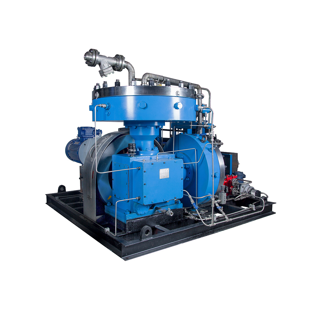
You need clean gas at the outlet, and the G110L Diaphragm Compressor delivers it through one simple principle. A hydraulically actuated metal diaphragm forms a solid wall between your process gas and the hydraulic oil. The gas never touches a lubricant. This design removes three contamination risks at once: lubricant contact, leakage, and purity loss. You can therefore compress high‑purity, corrosive, toxic, and hazardous gases with confidence. The metal barrier keeps the gas stream sealed and unchanged from inlet to outlet. That physical separation is the heart of the solution.
Key Takeaways
- A metal diaphragm separates gas from oil, so your gas stays clean.
- The G110L compressor handles corrosive, oxidizing, hydrogen‑brittle and toxic gases safely.
- Maximum discharge pressure up to 100 MPa; flow performance depends on configuration and operating pressure.
- Industries like semiconductor and medical rely on this oil‑free design.
- Xuzhou Huayan provides certified support and customized solutions worldwide.
Why Traditional Compressors Contaminate Gas
Lubricant Contact in Oil‑Lubricated Designs
Most conventional compressors use oil to lubricate moving parts and seal gaps. That oil sits close to the gas path, and some of it escapes as oil carryover. You then face a hidden cost: the gas leaves the machine dirtier than it entered.
Industry groups treat oil carryover below 25 parts per million by weight as a standard benchmark. Many electronics and pharmaceutical processes demand even lower levels. Trace oil damages sensitive components in semiconductor fabrication and circuit board assembly. It also reduces product reliability and yield rates. Food and beverage plants must meet FDA and HACCP limits on oil in air that contacts food. Pharmaceutical production needs exceptionally clean air under GMP rules to protect drug safety and efficacy.
Leakage Paths and Purity Loss
Oil‑lubricated designs also create leakage paths. Shaft seals, piston rings, and gaskets wear over time. Each worn seal lets process gas escape or lets outside air creep in. You lose purity at the outlet, and you may lose expensive or hazardous gas to the atmosphere.
The damage spreads downstream. Oil carryover contaminates piping, valves, and instruments. Air quality drops, equipment suffers damage, and maintenance costs rise. For a toxic or corrosive gas, a leak is also a safety concern. These problems compound in high‑purity work. A small leak at the seal becomes a large purity problem at the point of use. Traditional designs fight these risks with filters and separators. Those add‑ons capture some oil, yet they cannot restore gas that has already picked up contamination. The root cause stays in the design: lubricant and gas share the same space.
How Diaphragm Isolation Stops Contamination
A Flexible Wall Between Two Zones
The diaphragm compressor splits its interior into two separate chambers with one flexible part. The hydraulic side holds oil that a piston drives. The gas side holds your process gas and stays fully sealed. When the piston advances, it pushes oil against the diaphragm. The diaphragm bends into the gas chamber, shrinks the gas volume, and raises its pressure. When the piston retracts, the diaphragm bends back and draws in fresh gas. The oil stays on its side. The gas stays on its side. The two never meet.
A hydraulic oil distribution plate beneath the diaphragm carries a precise grooved pattern. This pattern spreads oil evenly across the diaphragm surface and prevents localized stress. Many designs use a triple‑layer diaphragm assembly with a process‑side layer, a middle monitoring layer, and a hydraulic‑side layer. Micro‑grooves between the layers form a leak‑detection channel connected to a pressure transducer. If the process‑side layer fatigues and gas begins to migrate, the transducer triggers an automatic shutdown.
The metal or elastomer diaphragm creates a complete, leakproof barrier between the gas and the hydraulic fluid/lubricants — this is its defining characteristic, enabling hermetic sealing.
Material choice matters for aggressive gases. Standard builds use 301 series stainless steel on the process side, with Inconel 718 available for chemical compatibility. A brass middle layer prevents galling between plates, and a 301 stainless lower layer separates the set from the hydraulic fluid. Process‑wetted components can also use Hastelloy, Monel, or PTFE to resist corrosion.
Zero Lubricant Contact and Zero Leakage
The cylinders in a diaphragm compressor require no lubrication. Your process gas therefore never contacts oil, and compression stays contamination‑free. This is what allows the G110L Diaphragm Compressor to handle high‑purity, sensitive, and hazardous gases without contamination or leakage. First‑party product claims for diaphragm hydrogen compressors state gas purity of 99.9999 % with zero oil‑contamination risk. Treat that figure as a product‑family claim to verify per model.
Leak‑free duty deserves careful proof. A diaphragm head provides strong process isolation, yet the full package still includes valves, fittings, instruments, relief devices, purge connections, and vents. Define leak‑free duty as a measurable requirement: tested boundary, test gas, pressure, method, instrument sensitivity, acceptance limit, and alarm proof. Ask for a witnessed factory report tied to the serial number and marked drawing. Every compressor is tested continuously for over 48 hours to verify performance parameters, and customers may witness the performance and running data.
Safety note for relief exhaust:
- Acidic/toxic gases such as chlorine: safety‑valve exhaust is routed to a dedicated caustic scrubber for neutralization, not direct atmospheric venting.
- Hydrogen: relief flow is directed to safe vent stacks or flare systems.
- Oxygen: relief exhaust uses oil‑free dedicated vent lines and must never connect to caustic scrubber systems.
Inside the G110L Diaphragm Compressor
Core Components That Protect Purity
The G110L Diaphragm Compressor is a positive displacement machine. A flexible, hydraulically actuated diaphragm separates your gas from the lubricated crankcase and piston. The hydraulic system pushes oil against the diaphragm, and the diaphragm compresses the gas on its own sealed side. Your gas never meets the oil. The cylinder head is water‑cooled, with five water channel holes and an external water cooler to control gas temperature. That cooling protects both diaphragm and valve life. An embedded double O‑ring design seals the head more tightly than an open membrane head.
Safety layers back up the isolation. The diaphragm uses a three‑layer structure with a rupture alarm. If the middle layer fails, a pressure sensor alarms while the outer layer still blocks gas leakage. A fixed gas detector on the skid monitors ambient concentration and interlocks with ventilation. Cooling water flow, oil pressure, and stage pressures and temperatures are monitored continuously with alarm and shutdown logic.
Performance Built for Demanding Gases
The platform covers a wide duty range. You can specify the machine to match your process rather than bending your process to fit the machine.
| Parameter | Specification |
|---|---|
| Model | G110L / G130L |
| Maximum Discharge Pressure (Design Pressure) | 100 MPa |
| Flow Range | 10‑200 Nm³/h1 |
| Piston Stroke | 110 mm‑130 mm |
| Motor Power | 7.5 kW‑90 kW |
| Maximum Piston Force | 20 kN‑40 kN |
| Crankshaft Speed | 420 rpm (rated reference speed) |
| Cooling Method | Cylinder head water‑cooled (standard); air‑cooled available for low‑power models |
| Inlet Pressure Range | Custom‑specified per process requirement |
1 Nm³/h at 0 °C, 101.325 kPa; for hydrogen refueling applications, flow may be referenced at 20 °C per station convention. Higher flow up to 1000 Nm³/h can be achieved via multi‑unit parallel configuration for low‑pressure operating conditions; high‑pressure single‑unit flow is limited to the above range.
Corrosion‑resistant and application‑matched materials let the compressor handle challenging gases such as chlorine, hydrogen and oxygen. Hydrogen service uses hydrogen‑embrittlement‑resistant materials; oxygen service applies strict oil‑free oxidation‑safe specifications; chlorine service uses high‑corrosion‑resistant alloys. Air‑cooled execution is only offered for low‑power variants. The high design exhaust pressure and strong sealing performance support reliable, long‑term operation with these gases.
Limits and Service Requirements
Diaphragm compressors deliver exceptional gas purity but have defined operating boundaries:
- Diaphragm plates and gas valves are consumable wear parts. Typical diaphragm service life is no less than 2000 operating hours; actual service interval depends on gas composition, pressure ratio, temperature and operating cycle. Spare‑part budgets and planned maintenance shutdown windows should be included in project planning.
- Single‑unit displacement is inherently constrained by diaphragm diameter and stroke length. Diaphragm compressors are best suited for high‑purity, moderate‑flow, high‑pressure‑ratio applications. For large‑volume low‑pressure‑ratio compression tasks, conventional piston compressors remain the preferred solution.
Standards & Compliance
Design and manufacturing follow multi‑standard requirements for mechanical, pressure‑vessel, hazardous‑area and process‑safety performance:
- Chinese mechanical & pressure‑equipment standards: JB/T 6905‑2019 Diaphragm Compressors; GB/T 150 Pressure Vessels; GB/T 20322‑2006, GB/T 25359‑2010, GB/T 41099‑2021, GB/T 7777‑2021, GB/T 4980‑2025.
- Application‑specific process standards:International references: ISO 9001:2015 certified; CE marked; pressure‑retaining parts available with ASME code stamping; designed in accordance with API 618 where project specifications require.
- Hydrogen systems: GB 50177‑2005 Hydrogen Station Design Specification, GB 50516‑2010 Technical Code for Hydrogen Refueling Stations, GB/T 43674‑2024 General Requirements for Hydrogen Refueling Stations.
- Oxygen systems: GB 50030‑2013 Oxygen Station Design Specification (referencing GB 8982 for medical‑breathing oxygen).
- Sour‑gas service: GB/T 20972.3‑2008 Materials for hydrogen‑sulfide‑containing environments.
- Explosion protection: GB 3836.1/.2 explosive‑atmosphere requirements with CNEx explosion‑proof certificates (Ex d IIB T4 Gb / Ex d IIC T4 Gb).
Proven Applications and Manufacturer Expertise
Where Purity‑Critical Compression Matters
Purity‑critical compression shows up across many industries. The table below maps where clean gas matters most, together with relevant governing standards.
| Industry | Purity‑Critical Gas Use | Governing Standards Reference |
|---|---|---|
| Semiconductor and electronics | Ultra‑high purity nitrogen, hydrogen, argon, and specialty gases for wafer deposition, etching, and lithography | Project‑specific semiconductor factory specifications |
| Oil and gas processing | Boosting and transporting natural gas streams containing hydrogen sulfide, carbon dioxide, water vapor, and sulfur compounds (desulfurization and decarbonization are separate upstream purification processes) | GB/T 20972.3‑2008 |
| Chemical and petrochemical | Purified hydrogen for ammonia synthesis, nitrogen for inert environments, and feed gas for cracking | JB/T 6905‑2019, GB/T 150 |
| Energy and hydrogen production | Hydrogen from steam methane reforming, electrolysis, or biomass, purified for fuel‑cell vehicles and energy storage | GB 50177‑2005, GB 50516‑2010, GB/T 43674‑2024 |
| Healthcare and pharmaceutical | Medical‑grade and pharmaceutical gases that meet strict regulatory purity standards for oxygen networks and hyperbaric chambers | GB 50030‑2013, GB 8982 |
Real installations prove the point. A diaphragm compressor at a hydrogen refueling station in Southeast Asia ran at 450 bar and reached 99.999 % hydrogen purity, serving more than 100 vehicles per day. Laboratories also rely on oil‑free diaphragm machines for ultra‑high‑pressure gases in spectroscopy and high‑pressure simulation chambers. Medical sites use oil‑free units complying with GB 50030‑2013 for oxygen networks and hyperbaric chambers. In each case, the G110L Diaphragm Compressor keeps the gas stream isolated from lubricants.
The Xuzhou Huayan Advantage
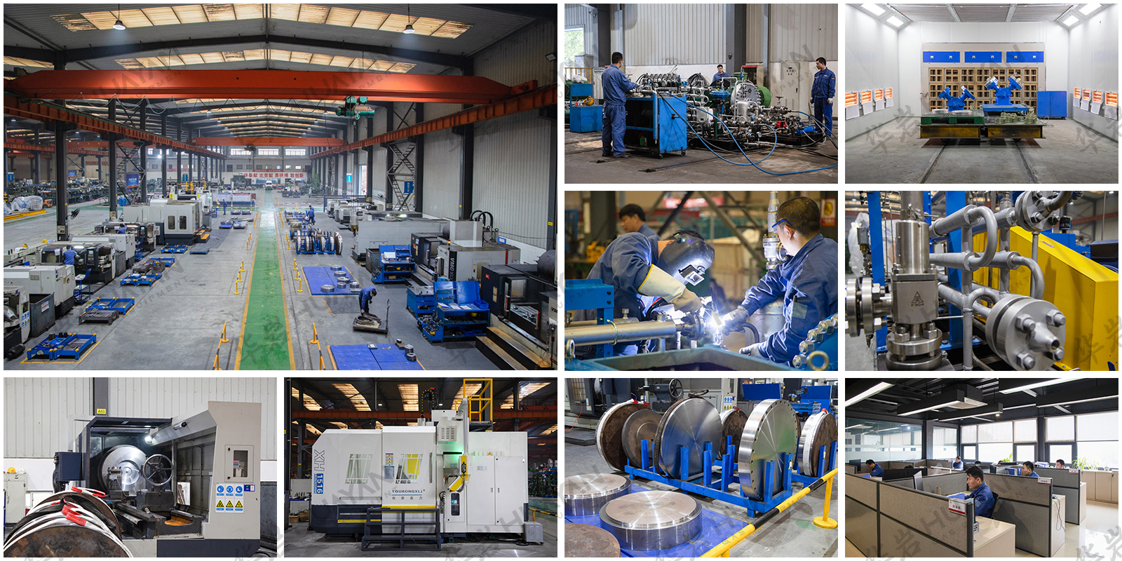
Xuzhou Huayan Gas Equipment Co., Ltd. builds the G110L within a cooperative factory covering 91 260 m². The company has manufactured diaphragm compressors since 1985, accumulating nearly 40 years of product experience. Advanced CNC machining and rigorous quality control support every unit. The company holds ISO 9001:2015, CE, and CNEx explosion‑proof certifications; pressure‑containing components can be supplied to ASME code upon request. That certification set opens doors to European, North American, and Middle Eastern markets.
The global footprint covers more than 50 countries across five continents, with over 500 active clients. Huayan Gas offers customized solutions for specific gas purity and pressure parameters. Turnkey support and responsive technical service back each project from order to startup.
The diaphragm’s physical barrier gives you three guarantees: zero lubricant contact, zero leakage, and stable gas purity. The G110L Diaphragm Compressor backs that isolation with real capability. It reaches design discharge pressures up to 100 MPa; single‑unit flow ranges from 10 to 200 Nm³/h (multi‑unit parallel for higher‑flow low‑pressure duties). Application‑matched materials handle challenging gases including chlorine, hydrogen and oxygen. These specs make the machine a strong fit for semiconductor, petrochemical, medical, and hydrogen‑energy work.
Xuzhou Huayan Gas Equipment supports every unit from its 91 260 m² facility. The company holds ISO 9001:2015, CE, CNEx and other key qualifications and serves customers in over 50 countries. You get customized solutions and turnkey support.
Contact Huayan Gas today. Share your gas purity and pressure requirements, and the team will match the right configuration to your process.
FAQ
A metal diaphragm separates the hydraulic oil from your process gas. The oil pushes one side, and the gas stays sealed on the other. The two never meet, so no lubricant reaches your gas stream. This physical barrier delivers zero lubricant contact and stable purity at the outlet.
Yes. Application‑specific material selections enable operation with challenging gases such as chlorine, hydrogen, and oxygen. Chlorine uses high‑corrosion‑resistant alloys; hydrogen uses hydrogen‑embrittlement‑resistant materials; oxygen uses strict oil‑free oxidation‑safe construction. A three‑layer diaphragm with a rupture alarm adds a safety layer. If the middle layer fails, a sensor alarms while the outer layer still blocks leakage. Relief exhaust handling is configured per gas hazard: scrubber neutralization for acidic toxic gas, safe flare/vent stack for hydrogen, dedicated oil‑free vent lines for oxygen.
The G110L has a maximum design discharge pressure of 100 MPa, and operating pressure is customizable within allowable limits. Single‑unit volume flow spans 10‑200 Nm³/h (Nm³/h referenced at 0 °C, 101.325 kPa; hydrogen refueling may reference 20 °C). Higher flow up to 1000 Nm³/h can be achieved through multi‑unit parallel for low‑pressure conditions. Piston stroke comes in 110 mm or 130 mm, and motor power ranges from 7.5 kW to 90 kW. Cylinder‑head water cooling is standard; air‑cooled execution is available only for low‑power models. Inlet pressure range is defined per project process requirements.
Semiconductor manufacturing, petrochemical processing, medical‑gas production, and hydrogen‑energy systems all depend on clean compression. Laboratories use oil‑free diaphragm machines for ultra‑high‑pressure work. Medical sites deploy units complying with GB 50030‑2013 for oxygen networks and hyperbaric chambers. Each case needs gas that stays isolated from lubricants.
Ask for a witnessed factory report tied to the serial number and marked drawing. Define the tested boundary, test gas, pressure, method, and acceptance limit up front. Every compressor runs continuously for over 48 hours to verify performance, and you may witness the performance and running data.
Diaphragm plates and gas valves are consumable wear parts. Typical diaphragm service life is no less than 2000 operating hours; actual service interval varies with gas composition, pressure ratio, temperature and operating cycle. Planned maintenance and spare‑part budgets should be included in project planning. Diaphragm compressors are best suited for high‑purity, moderate‑flow, high‑pressure‑ratio scenarios.
Post time: Oct-23-2026